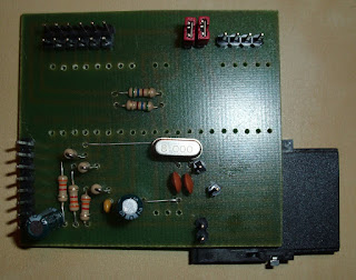
I would like to show you my new project. Shortly speaking it will be portable, battery powered C64 personal computer. I am a big fan of the C64 device. My codding begun on this device. I have one C64G device which I will modify a lot :) and post here a description of my work progress.
Small video.
So what we have now?
- SD2IEC
Mini LCD screen
Build-in amplifier
Stereo SID
- JiffyDOS
Battery power
I connected cheap lcd car display used for back camera. This device have AV input so it was really easy to connect it. I removed all not necessary stuff and left lcd panel and electronics board which is mounted inside the C64. The lcd is powered from C64 board from 9V DC source used mostly for SID. If I have some time I will post photo where you can find this on board. Ok, so here you can find photo of the power source. 2. SD2IEC
I mounted sd2iec on prototype board to check if it is working correct before I will make this device on PCB. I mounted this version. Most updated version of firmware you can find here. I used LarsP version of firmware which is correct for this layout. First you need to burn bootloader (newboot* file). I used this avrdude command to burn it : "avrdude -c usbasp -p m644p -U flash:w:newboot-m644p-larsp.hex:i -U hfuse:w:0x92:m -U efuse:w:0xFD:m -U lfuse:w:0xEf:m". After doing it put latest *.bin file to the root directory of the sd card and after turning on the device it will update the firmware. Board is working correct so I am planning to build one layer PCB for it. Ok so here is a current PCD work progres :) I am almost ready with my layout. The thing is to use not smd elements but to get small compact board that is possible to do by thermic transfer. This is final version of the PCB. The idea of this board is "use what you need". If you plan to use SD card reader and slot from it connect directly to the pins on the left side and connect sd card detect and sd write protect pins and 3.3V source from reader (remove Q1). If you plan to mount sd slot on pcb then solder it on right side and connect by wire sd7, sd5, sd2, sd1 signals from left to right. If slot have "card detect" and "write protect" pins connect it to the corresponding pins on top. For most of the MMC slots and some SD slots you should be able to solder it to PCB. After first run I found small error in PCB. Boards below are OK. Please make sure that you solder Q1 correct because I mess up pin layout. R1, R2, R3: 1.8k R4, R5, R6: 3.3k R7, R8: 560 C1, C5: 100n C2, C3: 33p C4, C6: 2.2u Q1: 3.3V Q2: 8MHz IC1: ATMega644P (5V) This is PCB done by thermic toner transfer. This is PCB after painting with the paint for glass. This is the trick to make DIY solder mask. And finally PCB after removing paint from solder pads. Here you can find current board look. This is fully mounted device. Ant the place where it will be mounted. Some links and places from where I get inspiration for my project: http://www.eltop.republika.pl/sd2iec.html (PL) http://www.pitsch.de/stuff/mmc2iec/index.htm (EN) http://www.c64-wiki.com/index.php/SD2IEC (EN)
3. Stereo SID
I have found some time at weekend and mounted Stereo SID module. Available addresses for second SID are: d400, d420, d500, de00, df00. I was thinking how to mount preamp for second SID and came out to the idea of cutting whole preamp from another c64 board. So I did it. You need to connect point A and B between two boards. C connected to pin 1,2,3,4 are 22nF (new SID) or 470pF (old SID). C in audio line is 100nF. Address for second SID is selected by 74LS139. I put another SID on existing one and solder it together according to schema below.


